
To make the technical explanation more visible, I have made some simple images to illustrate what happens. The images below picture one 1×1 degree tile and the rows are the lines in the scenery_packs.ini file that define the load order.
Simple basic situation
First the most basic situation in X-Plane: 3 airports without any airport ‘mesh’ with the default brown mesh at the bottom:
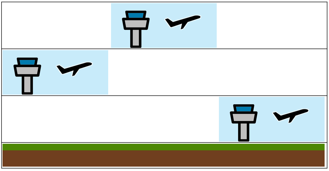
In X-Plane you will see this as a result (all good):

Airport packages with polygons
Now we take 1 simple airport package and 2 airport packages with polygons that ‘paint’ the ground with satellite images. Important: as explained this is technically not ‘real’ mesh! The polygons have a green color:

In X-Plane you will now see this (all good):

Underneath the green polygons the default brown mesh is loaded by X-Plane, but as a user you cannot see this.
Airport packages with real mesh
The last example is what happens if an airport package with real mesh is placed high in the ini order. The airport mesh (for real this time) has an orange color:
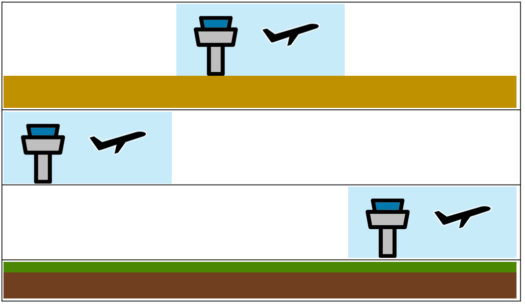
And in X-Plane this will happen (not good):

As you can see all other stuff in the same 1×1 degree tile but lower in the ini order is overwritten and not visible. This will be true for objects, polygons, networks and other mesh (all defined in DSF files).
BUT: you will still see everything that is defined in the apt.dat files -> so, runways and taxiways will be visible!